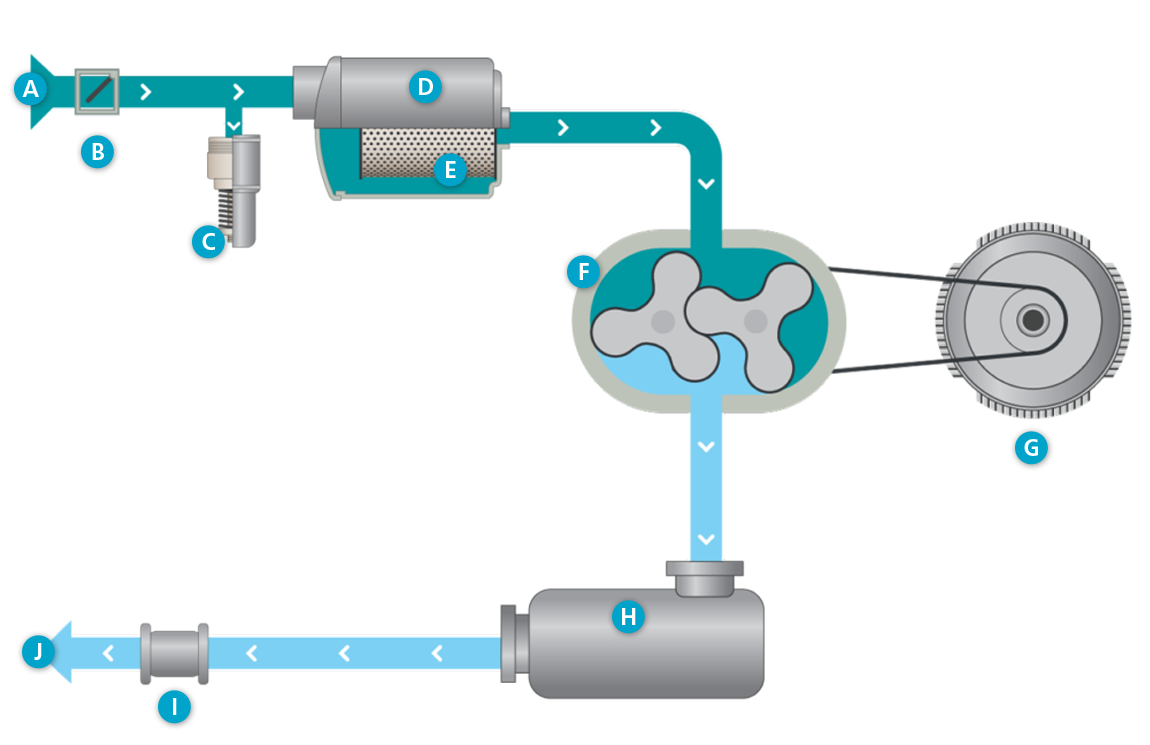
Vacuum flowchart

A. Air inlet
B. Check valve
C. Vacuum safety valve
D. Intake silencer
E. Intake filter
F. Oil-free lobe blower element
G. Motor
H. Pulsation damper
I. Compensator
J. Air out
 Vacuum air
 Atmospheric air
Cooling flow
A fan forces fresh ventilation air in the canopy, through a noise attenuating baffle system.
Cubicle ventilation air is mixed with the canopy ventilation air.
The motor cooling fan circulates this fresh canopy air over the motor housing,
The motor fan-cowl ensures that air flowing over the motor cooling fins.
The forced ventilation flow through the canopy removes the heat radiated by the blower core.
The hot canopy air can leave the canopy through a grating at the side panel.
Process flow (intake)
The process air is entering blower unit via flexible suction connection, the air is filtered prior to entering the lobe blower element. The filter housing reduces the inlet pulsations.
The lobe blower element moves air from inlet to outlet.
Discharge silencer reduces the pressure pulsation levels to the minimum.
The vacuum safety valve is pushed to be opened by the increased vacuum at suction side and sucks air from the ambient. In a normal operation within vacuum limit settings is closed.
Process flow (discharge)
In case of vacuum mode the exhaust air on the discharge flange of the blower unit is useless. To avoid noise excessing in a place of the blower installation is recommended to a connect discharge flange with exhausting pipe or with additional outlet silencer. With additional piping has to be ensured adding minimum pressure drop.