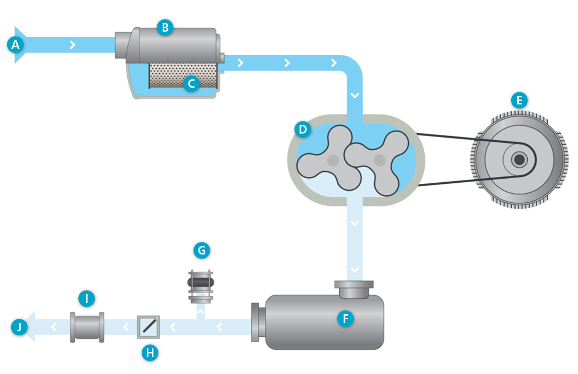
Overpressure flowchart

A. Air inlet
B. Intake silencer
C. Intake filter
D. Oil-free lobe blower element
E. Motor
F. Pulsation damper
G. Vacuum safety valve
H. Check valve
I. Compensator
J. Air out
 Atmospheric air
 Compressed air
Cooling flow
- A fan forces fresh process and ventilation air in the canopy, through a noise attenuating baffle system.
- Cubicle ventilation air is mixed with the canopy ventilation air.
- The motor cooling fan circulates this fresh canopy air over the motor housing, The motor fan-cowl ensures that air flowing over the motor cooling fins.
- The forced ventilation flow through the canopy removes the heat radiated by the blower core.
- The hot canopy air can leave the canopy through a grating at the side panel.
- The hot air blown out by the startup and safety valve is ducted straight out of the canopy to avoid canopy heating.
Process flow (intake)
- A fan forces fresh process and ventilation air in the canopy, through a noise attenuating baffle system.
- Air is filtered prior to entering the lobe blower element. The filter housing reduces the inlet pulsations.
- The lobe blower element moves air from inlet to outlet.
- Discharge silencer reduces the pressure pulsation levels to the minimum.
- At start-up, the blow-off valve is “open” for smooth unit start-up. That valve closes itself, pushed by the increased air pressure.
Process flow (discharge)
- As soon as the blow-off valve is closed, air pressure increases further, resulting in enough force to push the check-valve open.
- Air is delivered to the system.