Oil and air flows: your step-by-step guide
ZT 30-55 FLX FF (iD) Flowchart Legend:
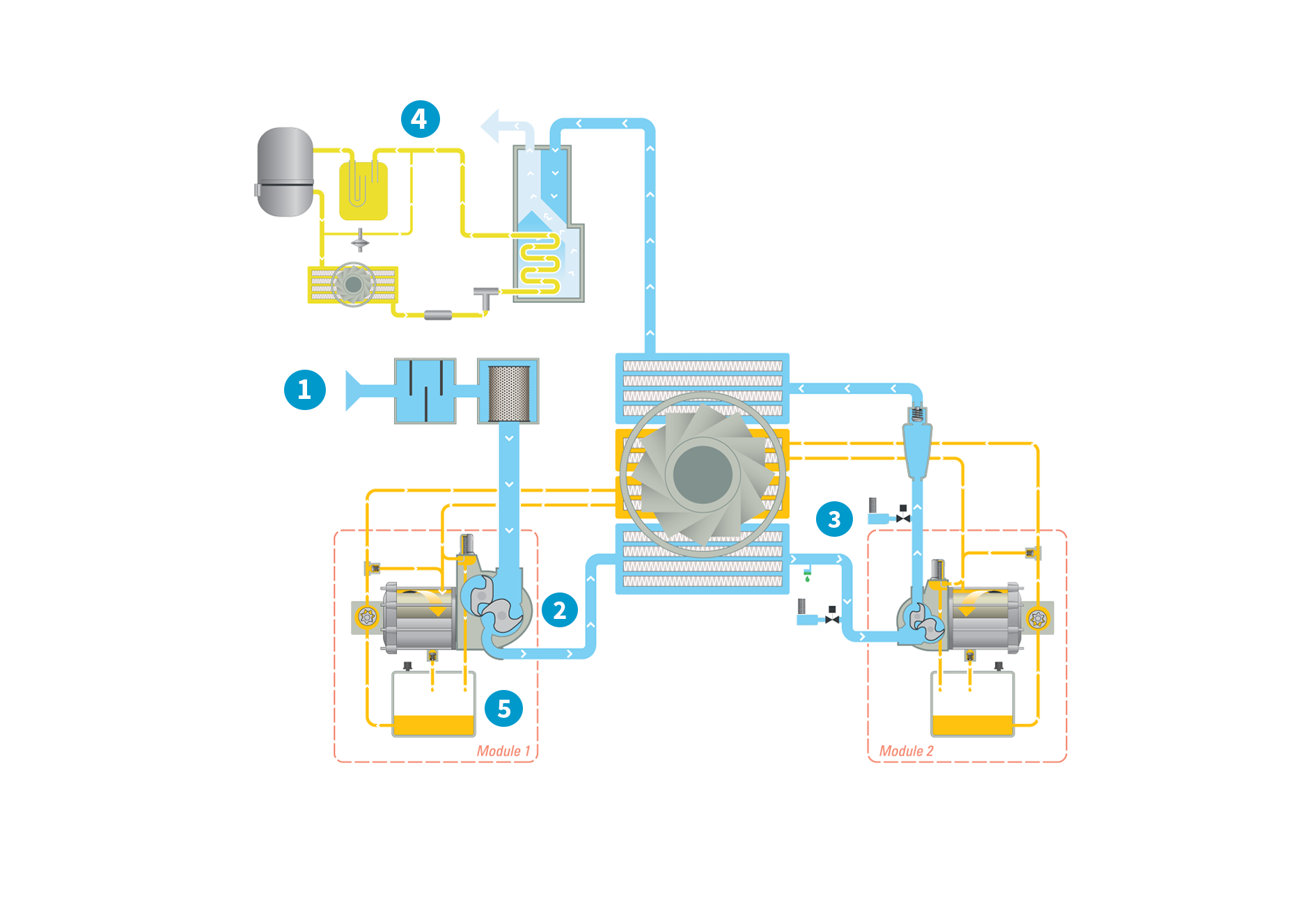
1. Inlet & filtration
2. First compression & cooling
3. Second compression & cooling
4. Integrated dryer
5. Oil flow
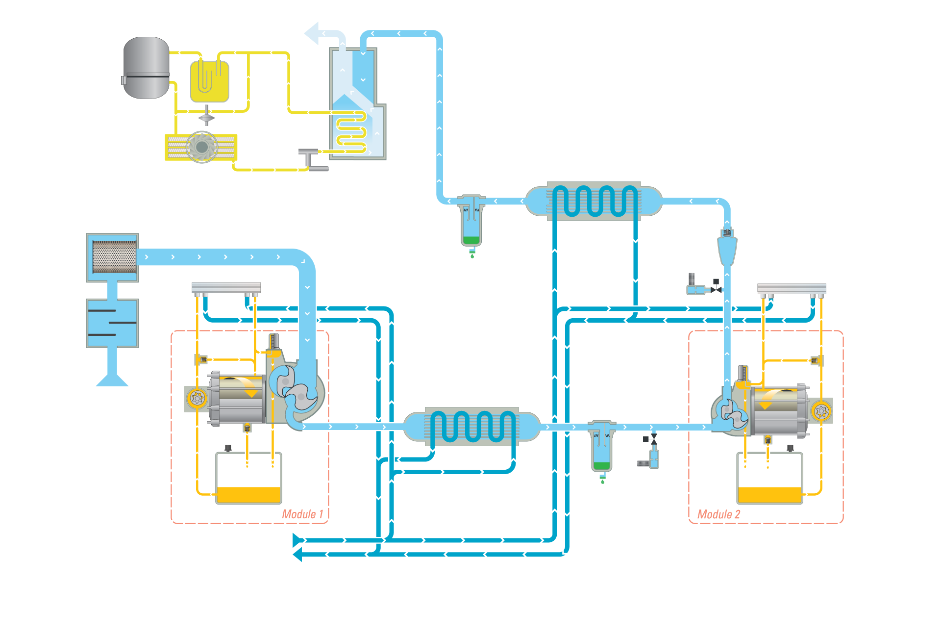
ZR 30-55 FLX FF (iD)
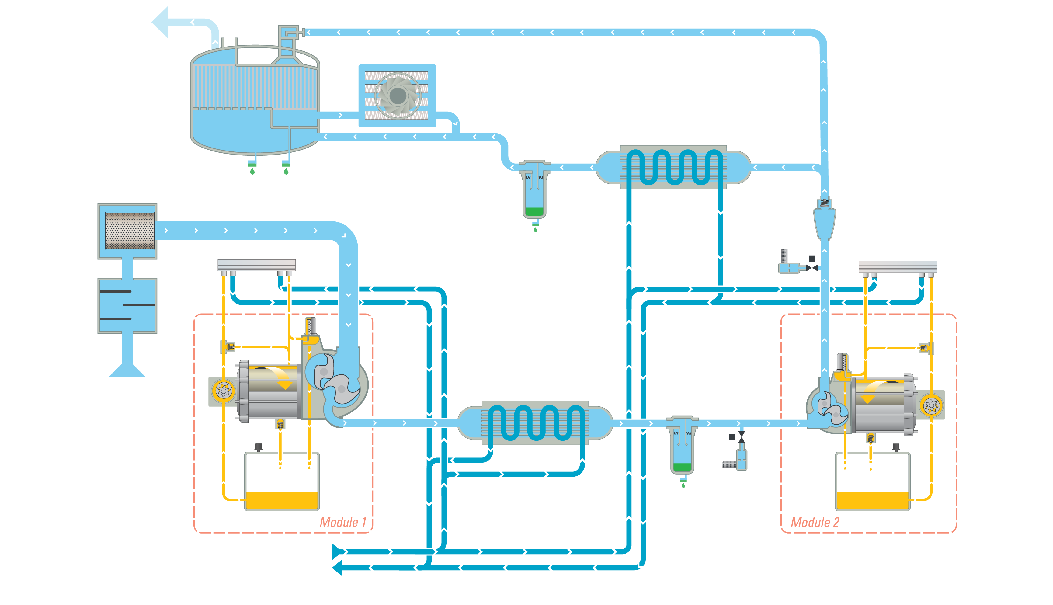
ZR 30-55 FLX FF (iMD)
Inlet & filtration
The air (represented by the light blue flow) is drawn into the compressor through the inlet filter, where it is cleaned. Then, it passes through the throttle valve with its integrated blow off valve which takes care of the load unload regulation. The air then continues to the compression stage.
First compression & cooling
The air pressure is raised to an intermediate pressure, after which the air is cooled down in the intercooler. Next, it passes through a moisture separation system before entering the high pressure stage.
Second compression & cooling
In the high pressure stage, the pressure is brought to the final pressure. The air at the outlet of the high pressure stage passes via the pulsation damper with integrated check valve to the aftercooler. Here, it is cooled down. Moisture is separated and evacuated. The compressed air leaves the compressor through the outlet connection flange.
Integrated dryer
The cooled wet compressed air is mixed with 40% of the cooled regeneration air. It enters the dryer. The dry compressed air with guaranteed dew point is now ready to use in your application.
Oil flow
The oil path within the compressor is represented by the yellow flow. The oil pump sucks oil from the oil sump and pumps it through the oil cooler and the high efficiency filter. This delivers cool, clean oil to the bearings and gears. Note that oil never comes into contact with the air. This ensures completely oil-free air for your process.